For the features that are common to all renderers, refer to the common features in the overview. What follows is specific to the Transfer Renderer.
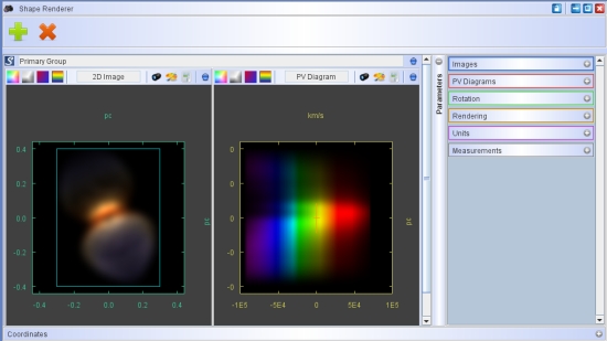
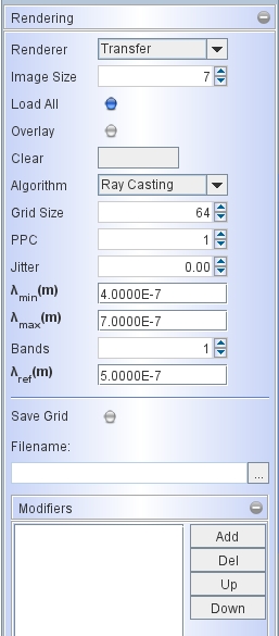
Currently, there is only one option for the rendering Algorithm, i.e. Ray Casting. For each image pixel, this algorithm casts a ray along the line of sight from the far side of the 3D grid and checks for cells that are located on this ray. If there is a cell, then it casts another ray to each light source, and calculates the radiation transfer from the light source to the cell to determine the local emission properties. Once the emission and absorption properties are known, the already accumulated emission along the ray is added taking into account the new cell's opacity. This procedure is done for each Band in the spectral range given by λ_min and λ_max, such that all physical properties can be wavelength dependend as set it the Physics Module.The wavelength λ_ref is the reference wavelength for velocity conversion of Doppler-shift calculations. This is used in the calculations of spectra and P-V diagrams.
There may be more than one light source (Emitter) in the grid. Note that, depending on the spatial distribution of the density structures, near the sources the angular size of cells as seen from the source may be large. Then the final result may depend significantly on number of cells in the grid. Therefore, if physically reasonable, it might be recommendable to include a small empty region (vacuum material) around the light sources such that the angular size of the innermost cells as seen from the source is adequate.
PPC (Points per cell): for some objects the sampling rate in the grid may not be sufficient. Instead of increasing the whole grid in size, one can apply additional sampling points in a cell. This samples the physical properties and the mesh at additional random positions. The properties of these points are then averaged in the cell.
Jitter: This parameter allows you to sample the grid cells at random positions. This help to reduce effects and artifacts due to the regularity of the base grid. Jitter takes values between 0 and 1.